Posts

Showing posts with the label Stools

Castings

Image
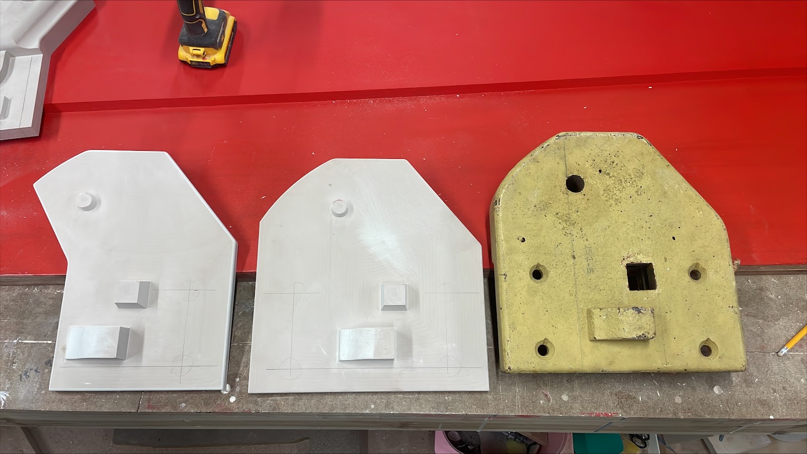
You may remember that we've been having various castings made for NER CD signal components, frame components, NER ND lattice parts and block shelf brackets. These have now been completed, and machining is well underway. On the CD signal component machining, the spectacles and back blinds have now been completed: these are now ready for painting! The spindles are almost complete, and the other parts just require holes drilling. Some of these are easy, some are causing a bit of head scratching, as they fit onto a tapered post, therefore require drilling at a corresponding angle to the taper. The carefully aligned key way in one of the backblinds The stack of spectacles>  **probably worth cropping down a bit! Are these the first NER CD components to be cast in over 120 years? The new grids for the top of the lattice posts: these hold the corners of the posts in position and support the finials on top One of the lever pivot supports was missing from the kit of parts. A replacement h...

Stake and Chips

Image
 ...no, not that kind of steak... nor the type used to dispatch vampires (although they are a similar shape)! A pile of recovered stakes In order to operate the semaphore signals from the box, wires are connected to the levers and run along to the signals by means of flat wheels (to change direction) and pulleys (held on posts) to travel the distance. It is these posts we are (well, primarily Matt is) installing. We recovered a large number of concrete wire stakes from Norfolk as part of a joint exercise in cooperation with various parties. Some of these had wire pulleys (or the remains of those) still attached. Timmy supervises the installation of the stake (whilst keeping well away from Barras) Having decided the principal routing for the signal wire runs, these stakes have been spaced along the run to support the wires for the signals. It is then a case of digging out holes in the ground to plant them in. It would be far easier to just stab them into the terrain (as the name sug...

The Rafters – Part 2

Image
Construction has begun once again on the signal box as the hand-carved decoration on the ends of the purlins has been completed allowing us to set them in position on the gable ends and begin cutting and fitting the rafters to the rear section of the roof. I think I mentioned previously that these rafters would require more than a little ‘fiddling’ to get a good fit and so it has proved. This has been compounded by the fact that the ridge timber, after a few weeks exposure to the Cumbrian sun and rain, has developed a marked twist at one end (please see the photo) which we will also now have to accommodate. Despite these irritations, we have now managed a satisfactory fit of a rafter at each end of the ridge leaving another nine required to fill the gap. I will keep you posted.

Rodding Run: 4 Rods Good...

Image
The rodding run continues to grow, heading towards the signal box steadily. In one of our last blog posts, we explained some of the difficulties in digging down deeper to plant the rodding stools...  Looking along the rodding from under the footbridge Having successfully planted these, it was time to drop the 4 rods onto them: a job Will had been very keen to tackle! First of all, he completed the installation of the a-frames, which bolt to the concrete stool. Then, it was a case of filling in the remaining hollows around the stools (which had been left to allow the bolts to be swapped over and tightened as required). Finally, the rods were placed into position, on a gentle curve which follows the track. These are not in their final places, longitudinally, as the benches and cranks have yet to be placed. This is why we've not yet fitted the top rollers. Looking down at the rodding from the recently-cleared cutting-top. Towards the footbridge, the rodding will cross underneath the t...

Ready For The Second ‘String’ Course

Image
After much preparation, we are now ready to install the final string course on which, the windows, and ultimately the roof, will sit. Although these are large and very heavy, we need to make sure there is no chance of movement when weight is applied. This photo and the ones below show the west-facing wall being built up and the repointed back wall. Consequently, we have been busy mounting various keys into the backs of the pieces of stone which, when enveloped by the concrete of the wall, will give us an immoveable base on which to mount the windows and then the roof. We have also begun to tackle the remaining panel of stonework on the west-facing wall which continues from where the windows finish to the rear wall and also rises to meet the cream bricks of the yet to be built gable end. So a lot is happening and there is still a lot to do so, as soon as there is more progress, I look forward to telling you more very soon!

NER Central Division Signal Components - Part Deux

Image
(Apologies for the Hot Shots reference with the title...) As a change from digging holes, this entry looks back at the Central Division (CD) components and what has happened with them. The arm weight we had originally hoped to cast from with minor attention, then machine out afterwards was not so simple, and instead required a pattern making to accommodate the voids / holes / undercut / pockets. Going down this route has caused extra outlay to have the pattern made, but brought down the cost of producing the components, as they will only require basic fettling and drilling as opposed to awkward machining. The more of these we have done, the greater the saving... Original arm weight (Right) Pattern for full size arm weight (Centre) Pattern for small (subsidiary) arm weight (Left) At the same time, we had a pattern made for the smaller (subsidiary) CD arm weight. These have now been completed, delivered to the foundry and successfully cast from! The extra lumps and hollows relate to wher...

A Rodding Run Odyssey

Image
Having dealt with all the levelling and aligning of the stools for the first section of the rodding run in the previous entry, we now wanted to get everything as "finished" as we could. We started by assembling the A-frames and rollers, then bolting them down onto the planted stools. The next stage was to tidy up the earthworks (the remains of the mole hills!) and leave a nice, smooth ground surface. The rods were then added, being slid onto the rollers and loosely bolted together to give a good idea of how it will look when completed. The rods will be adjusted once the cranks, compensatory and all the benches are in place, but to do any more at this stage would tie us up in knots! Finally, we disposed of the excess soil / ash / muck / digging to help build up the embankment near the Junction box, making the ground frame's rodding run a better product. We also had time to shift the next 5 rodding stools into place, ready for the moles to get busy once more. Time was also ...

The String Line

Image
Our last report of progress centered on the rough planting of stools for the rodding run. We had dug holes at regular 9' intervals to approximately the correct depth, and deposited concrete stools into these excavations.  No need for a gym membership. Next comes the process for aligning and levelling them up: the straighter the rodding run, the easier it will be to operate as friction and strain is minimised, so the incentive is there to do it really well, once, and not have to keep coming back to alter it later on! First of all, we set the two ends of this stretch of rodding: the alignment is taken from the Tebay line, whereas the level is taken from the (slightly lower) Penrith / Eden Valley line. It had to be this way around, as the EVR line will be slewed slightly later on as part of Permanent Way (track) work associated with the project. With the Cumbrian weather having filled the stool holes, baling out was first required! Bailing Out With the ends set, we borr...

Stools, Stools and More Stools!

Image
We have now reached the half way stage with the digging of holes for rodding stools. We have successfully dug 15 holes through all sorts of ground conditions, marking the half way point in the rodding run from the S&D box to the end of the shed crossover. This run will also incorporate a re-jigged ground frame for the turntable road. One of KSE's moles! The differing layers we have to dig through. Some are far tougher than others! However, these are only roughly dug, and the stools we have deposited now require squaring up, aligning exactly and levelling. The better and more accurately constructed the run is; the easier it will be to operate and look after. Molehills/stools A different view of the run so far Since we have reached the half way stage, we will tackle the alignment of these as the next job. The molehills will therefore disappear, and things will look far tidier! The water is a constant battle. Hopefully the levels will recede enough to allow the fine tuning of the ...

A Stool Sample...

Image
The majority of the blog's focus has (quite rightly) concentrated on the signal box rebuild by Bob and his team. However, there is a lot more to the project, and one section of that is how the signal box actually controls the points... For the crossover between the Tebay line and the headshunt / shed, this is achieved mechanically, using point rodding. The point rodding we are using takes the form of a channel, which is supported on rollers, which sit on top of concrete stools which in turn are set into the ground. The point rodding comes in 18' lengths, and we are setting the stools at 9' intervals to best support it and make sure the joints (which are fishplated) do not foul the rollers. There will be 3 rods involved for this: 3 levers' worth. It was felt that splitting the two turnouts on to individual levers would mean they were easier to operate (lighter to pull), and the third lever is the facing point lock on the Tebay line. These will be explained in greater det...