Hello all!
Today we're going to show how the unique North Eastern Railway Central Division level frame recovered from Pesspool Junction will be fitted into the S&DR signal box.
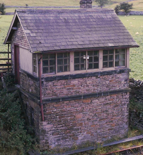 |
The 1861 box at the end of it's life.
Note the additional window to the locking room,
seen on the left hand wall in this picture. |
This is the
operating floor plan showing aperture for frame and *indicative* joist locations to accommodate this.
Dimensions:
Apologies: all dimensions used here are imperial as the equipment and building itself looks to
have been designed and built using these. They also work out very nicely!
Front to back, the surviving box structure measures 10’ inside the walls. This has been used in
this plan, and is assumed to be correct.
The aperture for the frame to sit is drawn here as being 6” from the front wall. This is our
datum, from which the other measurements are derived. This can be adjusted plus or minus 2”,
but will then shuffle the rest of the aperture across. If it is less than 6”, we have a much harder
time downstairs fitting in the pulley wheels required.
The 10’ length of the aperture for the frame is assumed to be central to the box, to allow access
Operating Floor:
The floor does NOT have to support the weight of the frame.
There are 4 stanchions that sit on the (green) RSJs which are located
under the box.
They are 5” wide (shown in blue), but are not spaced exactly equally throughout
the frame.
The 22 levers are split into 7-, 8- and 7-lever segments.
From these stanchions, the (darker blue) frame steadying brackets are through-bolted to the
joists on the front of the frame, and ideally through-bolted to the rear of the frame, but could be
coach-screwed instead. These in turn support the missing bits of the floor, which double as lift-up
access hatches to expose the mechanical locking for maintenance. All the weight of the frame is
taken through the cast stanchions (under compression), through to the RSJs below. (We have
not specified these channel sections per se, but they are at least 4 inches wide, by 10-12” deep.)
The longitudinal (lighter blue) strips sit on top of the stanchions (through-bolted), keeping them
vertical, and spaced, as well as supporting the lever quadrants. The area these fill is the other
shade of blue!
The orange coloured lumps are just a representation of the joists for the rest of the floor: they
only serve to show the aperture for the frame (120” x 64.5”)
 |
The upper part of an identical frame (just
about)
still in situ at Broomielaw.
|
Downstairs (locking room) door:
To enable this to open fully and allow access, the door needs to open outwards, hinged from the
rear-most (of the box) side. If it opens inwards, it will *just* be foul of the end stanchion of the
frame. This assumes the doorway goes in 42” from the back wall as the current stonework
indicates.
 |
Underneath the box, looking up at the frame.
|
This next image is the vertical cross section of the frame
and associated supports.
DATUM: Front edge of frame aperture in operating floor 6” in from the inside of the front
wall. This can be + or - 2” to cater for any other variations, as noted on the previous page.
DATUM: Vertical - top of sleepers. As drawn it ensures the top of the sleepers match the top
of the lead out bench and the top of the locking room floor. HOWEVER, this can be up to 5”
lower than the sleeper tops, but NOT HIGHER (to cater for any issues with the operating floor
height in relation to the box structure..
The frame ‘steadying’ brackets bolt to the joists. These also support the access hatches above.
The void below the locking frame floor and lead out bench is required to allow the bolting of
the components onto the bench. As the rear of the box should not have such a requirement, the
dug out void below can be less. The pairs of supporting rails should be built in / secured to the
front and rear walls of the box. (3 pairs, spread as in scrap view below. A 1” gap between the
rails is required.)
The lever frame stanchions are mounted on two channels (shown in green), running the full
length of the box. These can either be set into the side walls of the box, or on pillars set just
inside the walls. Tie bars (shown in pink), bolted or welded underneath, between the channels
can be used to keep them together and true for the installation, as these will not interfere with
the frame construction above.
Rodding / wire aperture in the front wall: 6¼” above the datum
Drainage: The box sits lower than the surrounding ground, and drainage will need some
consideration: probably running along the cess towards the drain at the end of the shed.
The following photos show how the drawings relate to the box structure itself.
 |
Looking at the remains of the back wall,
we took this level to be the original operating floor level,
which is 8’ above the locking room floor / top of sleepers
 | Using a laser level from top of sleepers of the
line adjacent to the box produces this level,
which becomes
top of locking room floor,
and the datum used in the
drawings. |
|
We hope that this post goes some way to help further your understanding of the project. We are all extremely excited and we'll be posting regular updates as they happen, right here! Feel free to comment if you have any questions.


.jpeg)

I wish I had the money to help you
ReplyDeleteIts wonderful to see the way you have approached this project with so much care and research. If only I could put a 200 mile fold in the uk roadmap!!
ReplyDelete