LMS Takeover Bid?
This blog post deals with something of an unsavoury nature: signals for our project that don't have any NER pedigree!
 |
| An LMS-designed single dolly at Kirkby Stephen West, on the Settle-Carlisle |
But don't be too concerned: the LMS-designed dollies are very appropriate for KSE, as there is at least one example pictured coming out of the mineral sidings near the Junction box, from the EVR line!
So, why did we choose to use them? Well, we have a fairly confined space beside the shed, where we need a number of signals in a fairly short distance. The LMS designed these ground signals (or dollies) that could be stacked on top of one another, following Midland and LNWR practices. The LNER design did not allow this, and instead you would place signals behind one another, set at different heights. We don't have the distances for that to work here, as we need two doubles, almost face to face, with a pretty short length of track between them. So, it's a case of "needs must", but it also has a historical precedent, and shows some of the variety of signalling there was at KSE.
We sourced all the components we needed to make both signals and set about freeing off pins and dismantling into component parts so that we could build them up as required. These originally came from Hitchin, and came to KSE via the Leighton Buzzard Railway a number of years ago.
 |
| Will freeing up pins in one of the balance levers |
As part of the components we found a clever slotting arrangement: one signal is controlled by two places, and both need to 'agree' for it to actually clear. Each lever controls one of the balance levers, and only when both are pulled, does an extra lever between them move and clear the signal. This is only relevant in that we have all the pieces, but want them to work in a different way... Looking ahead to Phase 2, some signals we're putting in now will need to be controlled by one box or the other. Effectively, by flipping one piece the other way up, we can achieve an "OR" function, instead of an "AND", in terms of logic...
 |
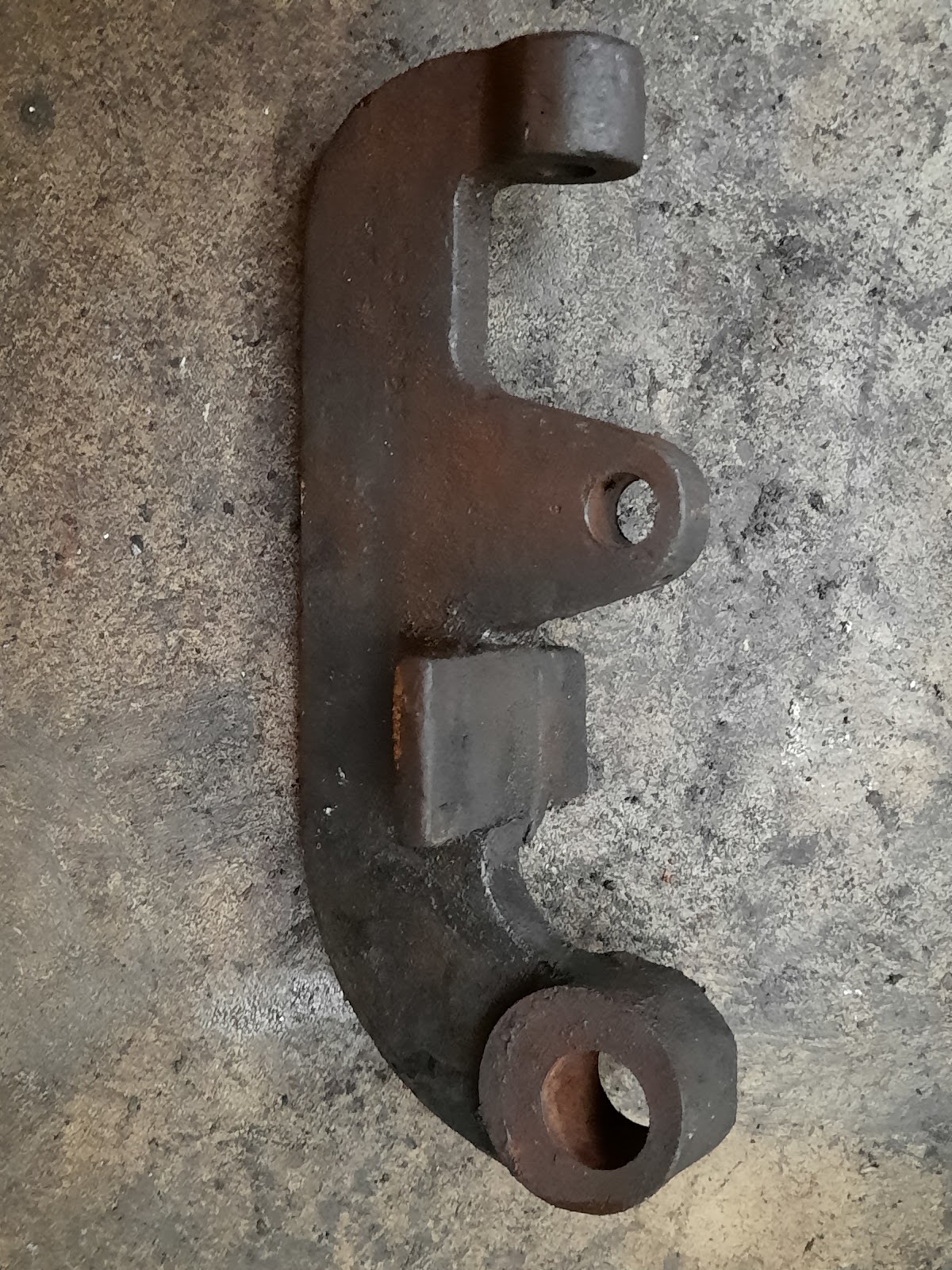
| The signal drive arrangement with its special 'flappy, dangling bit' |
We now have a roughly-assembled double dolly so that we can demonstrate its use and develop an appropriate dual control assembly, based on the original slotting.
 |
| The double dolly from the front, minus the discs themselves |
 |
| The four separate balance levers are clear to see, even though they only drive 2 discs |
Sadly it proved impossible to just flip the drive the other way up, as it catches on the main casting of the signal itself. However, this component (having been carefully stripped down) will allow for a prototype to be made from plywood to test my reckoning. More will follow on this endeavour in a couple of weeks.
 |
| Signal drive with the technical bit removed |

.jpeg)

Comments
Post a Comment